Sniffing BitLocker Keys from TPM
Extracting BitLocker keys from a stolen device's TPM to gain an authenticated foothold to a Windows Active Directory
So… I managed to extract BitLocker Volume Master Keys (VMKs) from a Trusted Platform Module (TPM) to break into a Windows system, dump hashes and get a domain computer account to hop onto my target’s AD as an authenticated user. This technique is effective against default BitLocker configurations that do not use pre-boot authentication like a PIN or startup key.
Introduction and Background
BitLocker is a full-volume encryption feature included with Microsoft Windows. In its default configuration, it uses a TPM to store and release the encryption keys automatically at boot. If there is no pre-boot PIN, this provides a seamless user experience that can also expose the encryption key to physical attacks.
The TPM is a dedicated microcontroller designed to secure hardware through integrated cryptographic keys. A discrete TPM (dTPM) is a physical chip soldered onto the motherboard. When the computer boots, the CPU asks the TPM for the key. The physical traces on the motherboard connecting them (usually an SPI or LPC bus) are completely unencrypted. If we hook a logic analyzer onto those bus lines during boot, we can sniff the Volume Master Key straight out of the air as it travels to the CPU, and use it to decrypt the Windows boot drive.
Note: This attack is only practical against discrete TPMs (dTPMs). Firmware-based TPMs (fTPMs), which are integrated directly into the CPU, are generally not vulnerable to this specific bus-sniffing technique (unless you are Ant-Man).
Breaking Down the Bus Signals
Before we start poking at motherboard pins, we need to know what we’re actually looking at. Discrete TPMs usually talk to the CPU over one of two buses: SPI or LPC. Here’s the quick breakdown of the signals we care about.
SPI (Serial Peripheral Interface) Bus
SPI is a synchronous serial communication interface used for short-distance communication, primarily in embedded systems. It operates in a main-secondary architecture where the main (CPU/Super I/O) directs communication with one or more secondaries (the TPM). The essential signals are:
- MOSI (Main Out, Secondary In): This is the data line that carries information from the main device (the CPU) to the secondary device (the TPM). When sniffing, this line will show you the commands being sent to the TPM, such as a request for the BitLocker key.
- MISO (Main In, Secondary Out): This is the data line that carries information from the secondary device (the TPM) to the main (the CPU). This is the most critical signal for this attack, as it is the line on which the TPM will transmit the BitLocker Volume Master Key back to the CPU after a valid request.
- SCLK (Serial Clock): This clock signal, generated by the main, synchronizes the data transfer between the main and secondary. All data on the MOSI and MISO lines is timed according to the rising or falling edge of this clock.
- CS (Chip Select): Also known as Secondary Select (SS), this signal is used by the main to select which specific secondary device it wishes to communicate with. When this line is pulled low (it is typically active-low), the corresponding secondary chip is activated. This is essential for isolating the communication intended for the TPM from other noise on the bus.
LPC (Low Pin Count) Bus
The LPC bus is a parallel bus used in PCs to connect low-bandwidth devices (like Super I/O controllers, BIOS ROM, and dTPMs) to the CPU. It was designed as a successor to the ISA bus but uses fewer pins.
- LAD[0:3] (LPC Address/Data): These are four bidirectional lines that are multiplexed, meaning they carry both address and data information at different times within a transaction. To reconstruct the full communication, you must monitor all four of these lines simultaneously. Both the commands to the TPM and the key sent back from it will travel over these lines.
- LFRAME# (LPC Frame): This is the primary control signal on the LPC bus and is active-low (indicated by the
#symbol). When the main pulls this line low, it signals the beginning of a new transaction cycle, or “frame,” on the bus. This signal is the equivalent of a “start” button for a bus operation and is essential for the logic analyzer to know when to begin interpreting the data on the LAD lines. - LCLK (LPC Clock): This is the main system clock for the LPC bus, typically running at a frequency of 33 MHz. It synchronizes all data transfers across the LAD lines, ensuring that all devices on the bus can correctly interpret the signals.
What You’ll Need (Hardware & Software)
To pull this off, you’re going to need a mix of physical gear and some analysis software. Here’s what I used.
Hardware
- Logic Analyzer:
- My Recommendation: Saleae Logic 8. This is every hardware hacker’s go-to. It’s incredibly user-friendly and handles this kind of work perfectly. The software for this analyzer supports the plugin we’re going to use out-of-the-box as well.
- Alternative: Just about any logic analyzer compatible with the Saleae Logic 2 software. Just make sure it supports a solid sample rate (at least 4x the bus speed), so aim for ~100MHz to be safe.
- Making the Connection: How you hook into the TPM depends on how the target motherboard is laid out. Here are the options:
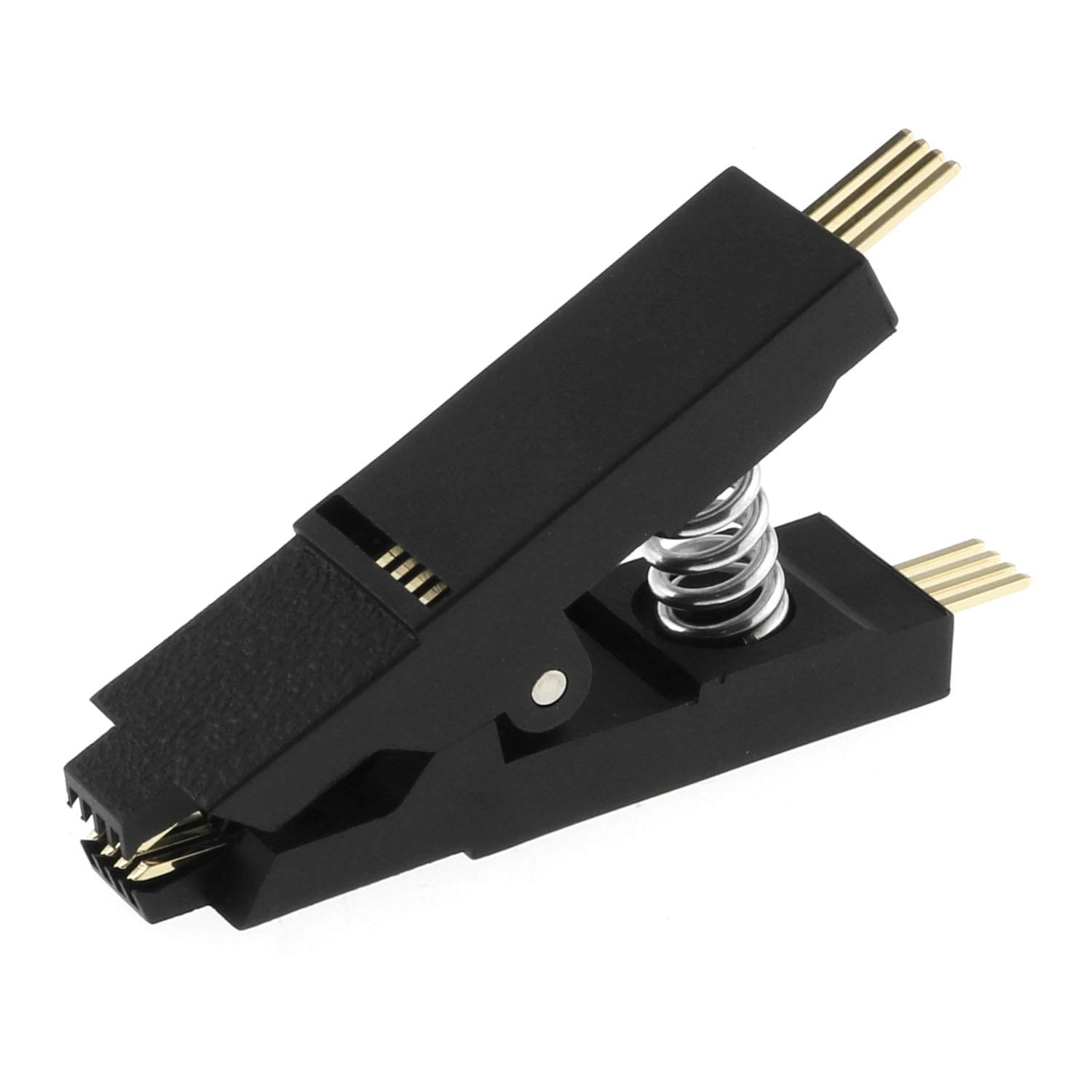
- SOIC8 Clip: If you’re lucky enough to have a TPM in a standard SOIC8 package, just pop a SOIC8 test clip onto it. No soldering, extremely fast, and non-invasive.
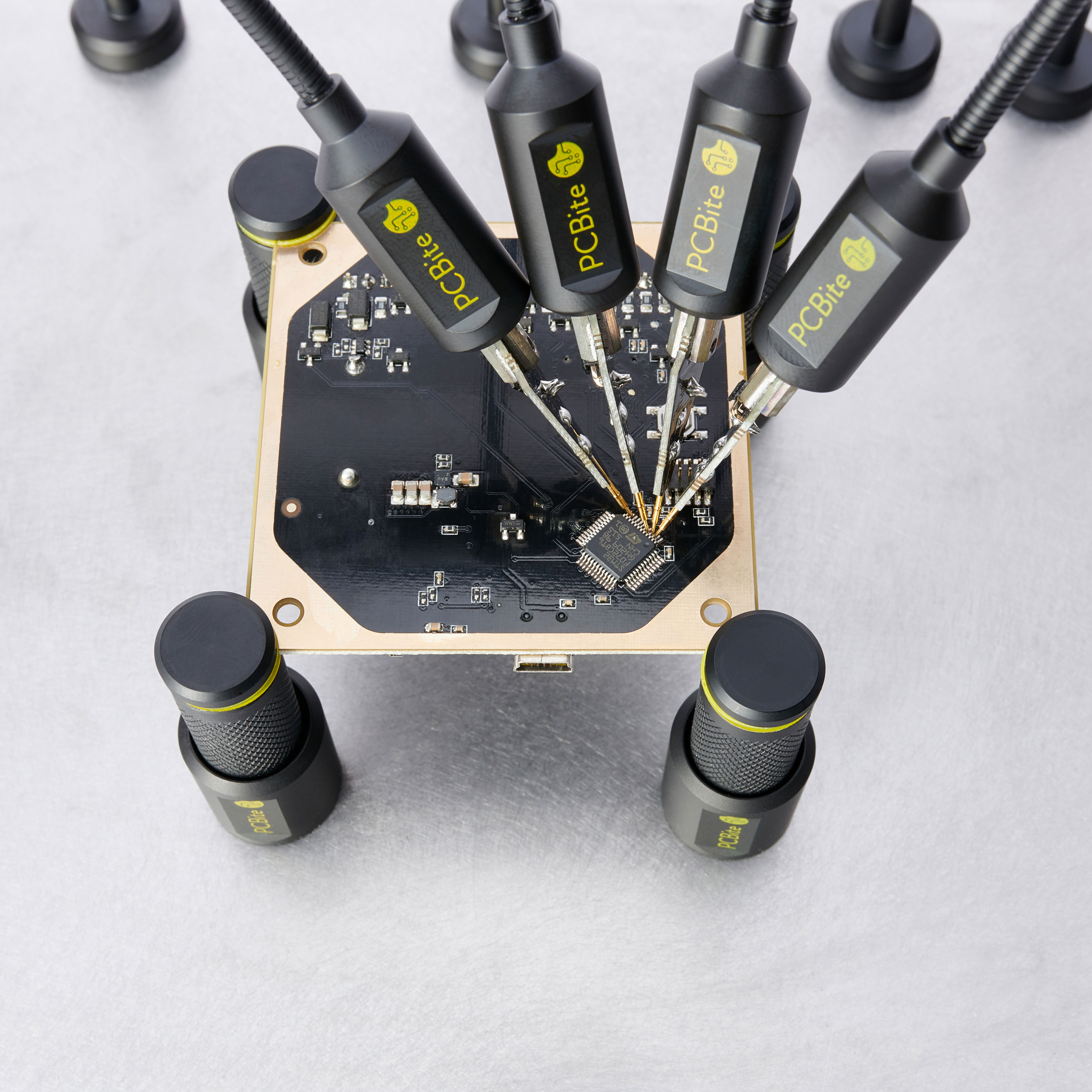
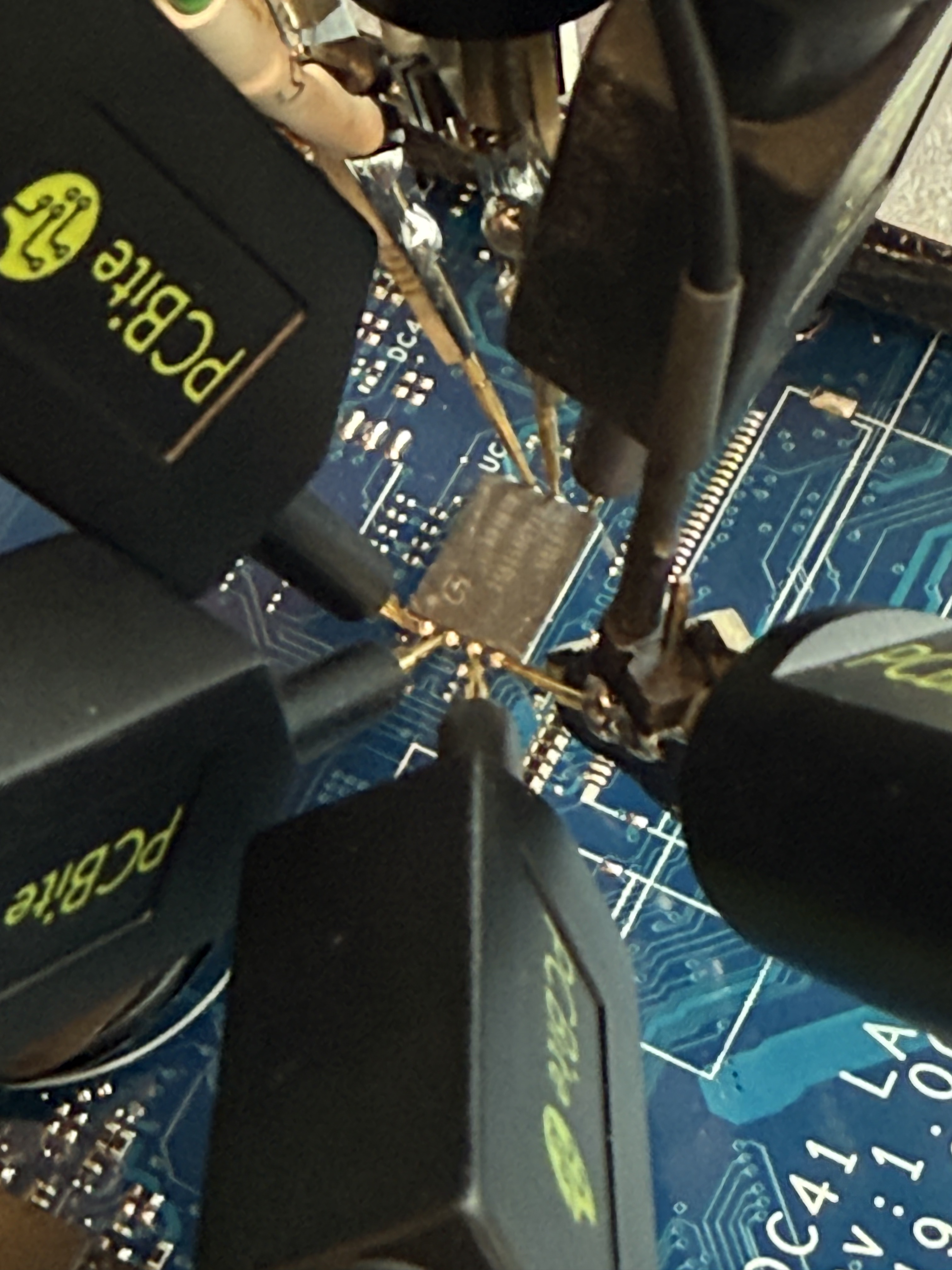
- PCBite Probes: If you need to hit tiny test points or vias, or just want to go with a gravity-assisted connection without soldering, PCBite probes are my preferred method. They’re super precise and hold steady.
- Soldering Iron and Micro-wire: Sometimes there’s no way around it. Sometimes you get super unlucky and you have to pray to your holy entity of choice and solder directly to the chip pins or tiny motherboards vias. Particularly terrifying if this is for a client of yours :). Grab a decent iron, flux, and some 30 AWG wire.
- SOIC8 Clip: If you’re lucky enough to have a TPM in a standard SOIC8 package, just pop a SOIC8 test clip onto it. No soldering, extremely fast, and non-invasive.
- Screwdrivers and Spudgers: Your typical electronics toolkit to open up the laptop or desktop casing without cracking the plastic.
Software
- Logic Analyzer Software:
- Saleae Logic 2: The gold standard here. It’s clean, easy to navigate, and has built-in protocol decoders for SPI and LPC.
- BitLocker Tools:
- BitLocker SPI Toolkit: An awesome GitHub repo with helper scripts to analyze the logic analyzer captures and isolate the VMK.
The Fun Part: Exploitation
Step 1: Recon & Finding the Target Chip
Our first job is to track down the physical TPM chip on the target board and figure out what bus it’s using. Do your homework online first before scraping probes across client hardware, it’s much safer.
Open the Case: Carefully disassemble the laptop or PC to expose the motherboard. Pro tip: take photos at every step of the teardown. If I have the time, I even print out a top-down view of the motherboard and place the screws in the corresponding places on that. Once you’re in, look for the motherboard’s model number printed directly on the PCB (like “
DA0X81MB6E0”). Write that down.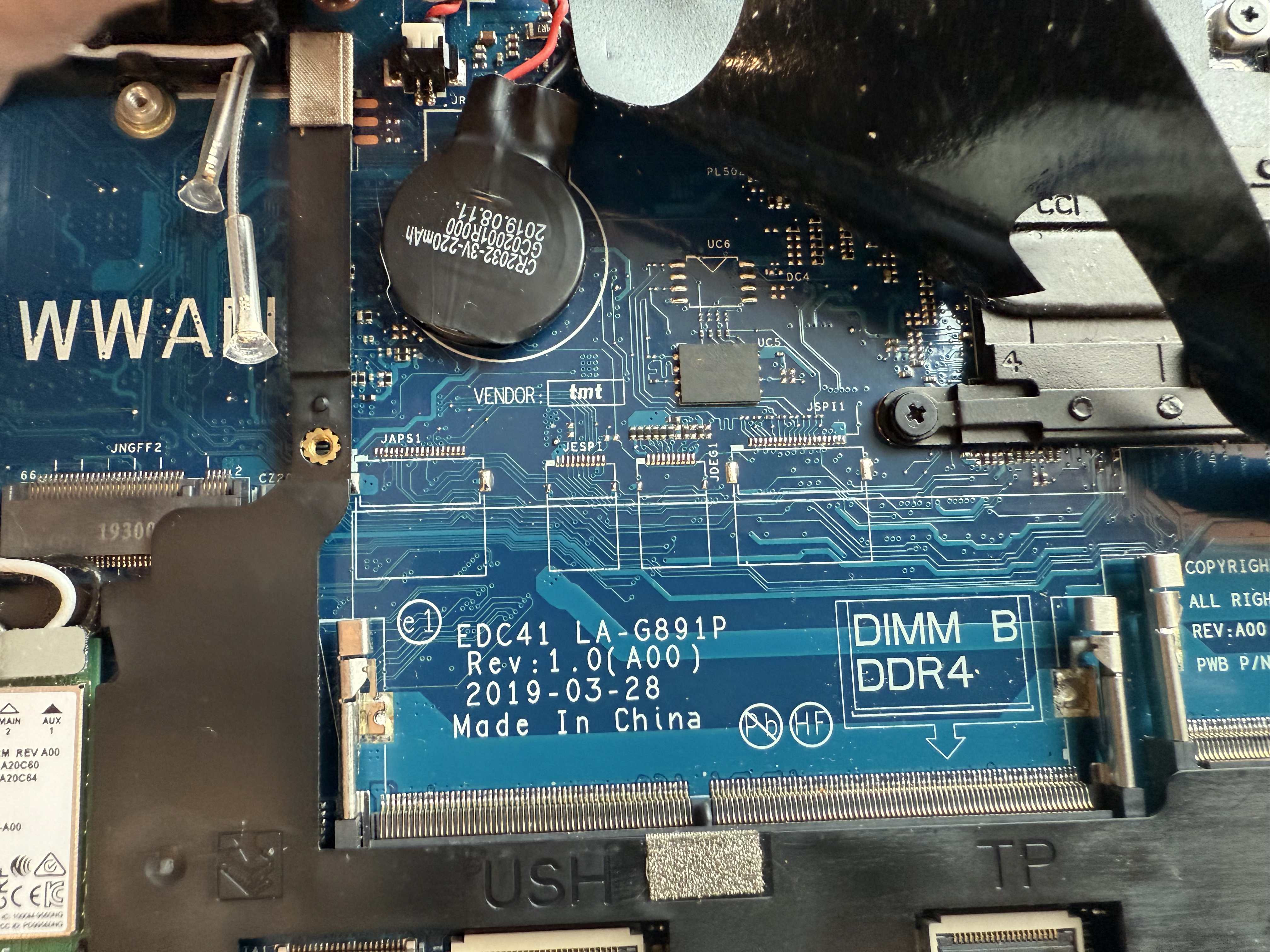
Google Dorking for Board Schematics: Use the motherboard model and Google dorks to dig up schematics or boardviews. This will hopefully save you hours of guesswork.
My favorite search dorks:
- For Schematics:
"[motherboard model]" schematic pdf"[laptop model]" schematicsite:vinafix.com "[motherboard model]"site:badcaps.net "[motherboard model]" schematic
- For Datasheets:
"[chip marking]" datasheet pdffiletype:pdf "[chip marking]" pinout
- For Boardviews (interactive board layouts):
"[motherboard model]" boardview"[motherboard model]" filetype:brd
Look through these files for terms like “TPM”, “SPI”, or “LPC”. The schematics you’re looking for will tell you which pins connect to which bus, and a boardview will point you directly to the physical spot on the board.
- For Schematics:
Find the TPM (or a Clever Alternative): Now look at the physical board. TPMs are usually small, square black packages made by Infineon, Nuvoton, or STMicroelectronics.
Pro tip: Fully stripping a motherboard is risky and tedious. If you don’t see the TPM on the accessible top side of the board, don’t pull the whole motherboard out just yet. Remember, SPI is a shared bus. Other chips on the easy-to-reach side might share the exact same SPI bus lines (like the BIOS/UEFI flash chip). Sniffing the pins on the highly accessible BIOS flash chip is often infinitely easier than digging for a hidden TPM on the underside, and gets you the exact same traffic.
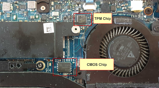
Identify the Communication Bus and Pinout: Confirm the communication bus type (SPI or LPC) and the exact pinout using the datasheet for the identified chip. This information is critical for correctly connecting the logic analyzer in the next phase.
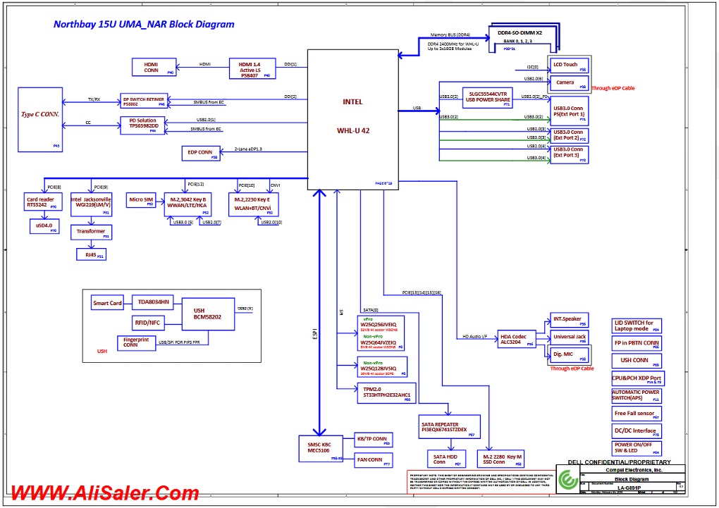
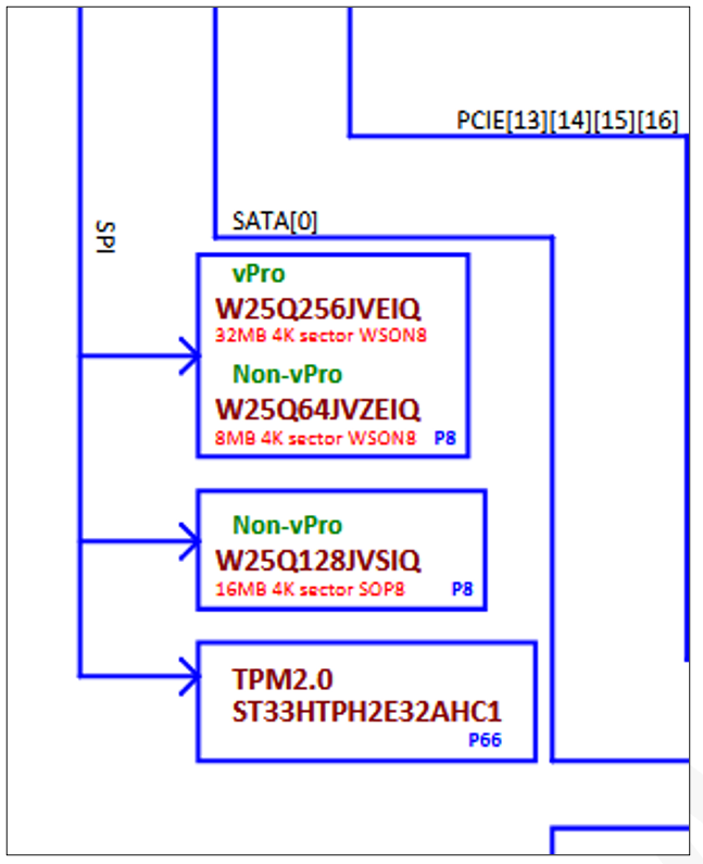
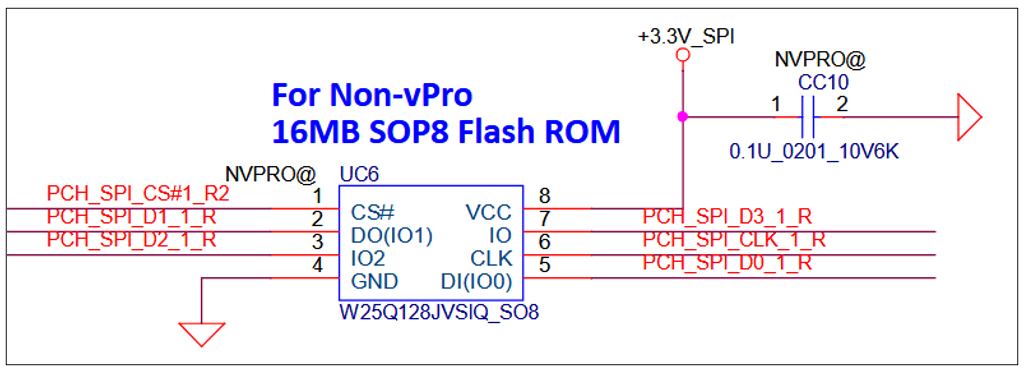
In the pictures above, you can see that the TPM chip and flash memory share the same SPI bus. In this example, the flash memory chip was much easier to get to, and there is an SPI pinout in the datasheet.
Attaching the Logic Analyzer
With the TPM chip and its communication bus identified, the next step is to connect a logic analyzer to intercept the data.
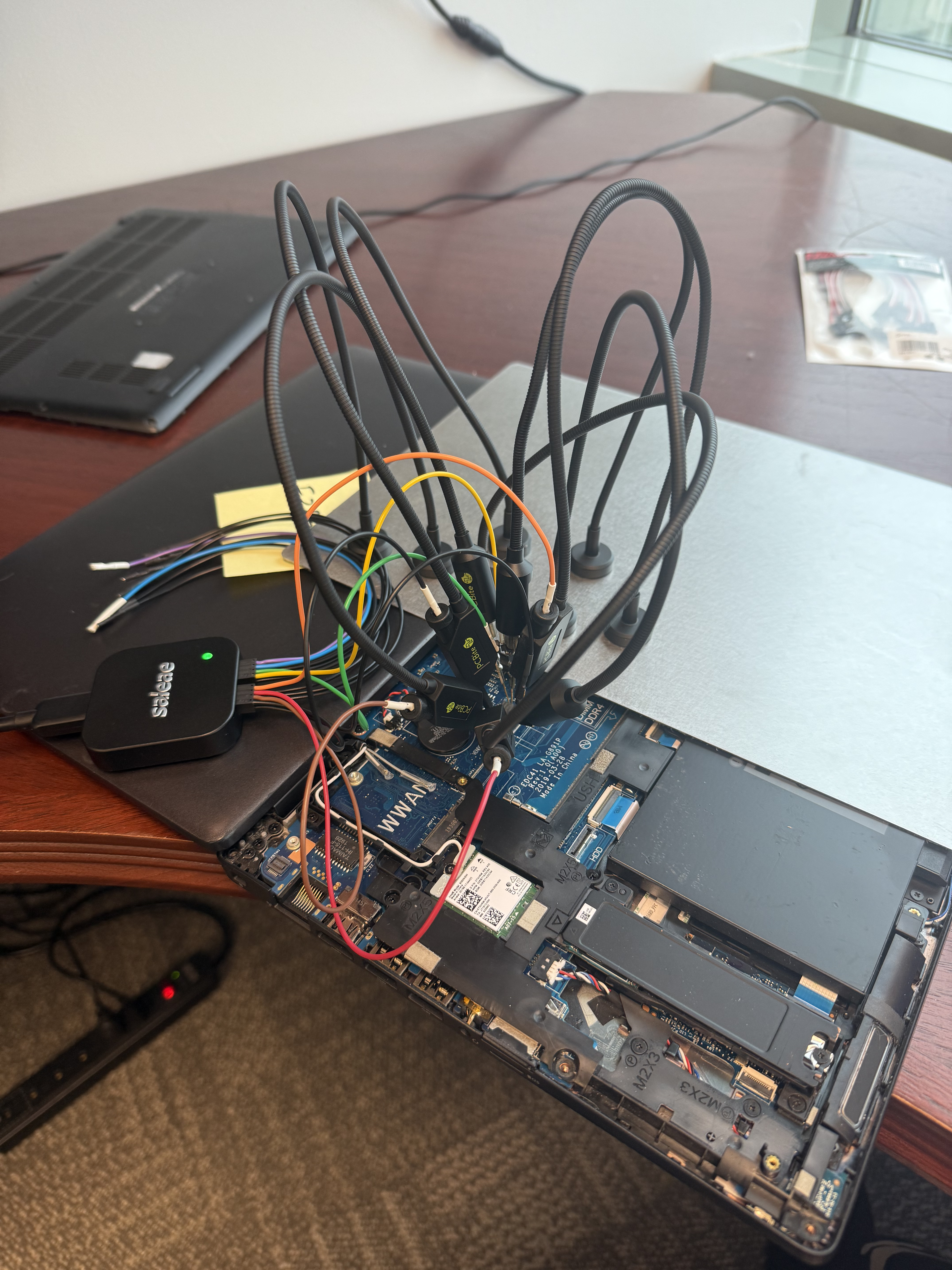
Prepare the Connection Points: You will need to connect probes from your logic analyzer to the relevant pins on the TPM chip or a nearby header. In some cases, you may find an unpopulated debug header on the motherboard that provides easy access to these signals.
Connect the Logic Analyzer: Use the SOIC8 clip/logic analyzer probes to make the connections or solder fine-gauge wires to the identified pins. Connect the other end of the wires or probes to your logic analyzer.
Data Capture and Key Extraction
This phase involves capturing the communication between the TPM and the CPU during the boot process and then analyzing the captured data to find the BitLocker VMK.
Configure the Logic Analyzer Software: Use Logic Pro 2 or the software provided with your logic analyzer to configure the capture settings. You will need to set the sample rate high enough to accurately capture the signals (e.g., 100 MHz for a 33 MHz LPC bus).
Capture the Boot Process: Start the capture on your logic analyzer and then power on the target device. Let the device boot into Windows. The logic analyzer will record all the data transmitted over the bus during this time.
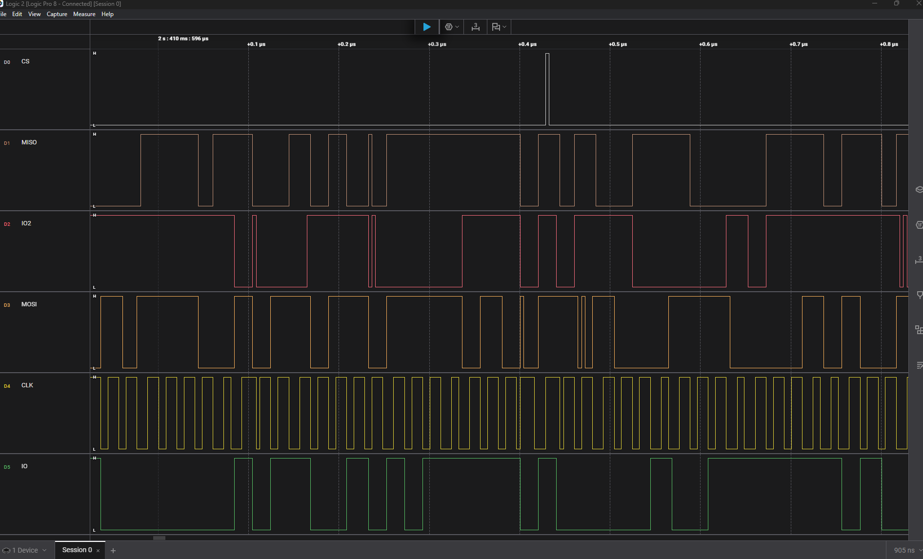
Decode the Captured Data: Use a protocol decoder to make sense of the captured data. For SPI or LPC, you can use the built-in decoders in your logic analyzer software. There are also specialized decoders available for TPM communications.
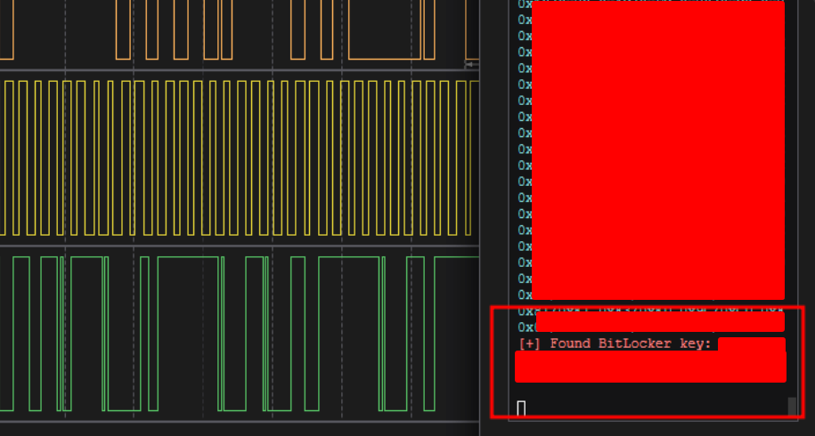
Extract the Volume Master Key (VMK): The VMK is what you are looking for in the decoded data. It is a 256-bit key that is sent from the TPM to the CPU. You can often find it by searching for a specific header or pattern that precedes the key. The BitLocker SPI Toolkit from ReversecLabs provides a Logic Pro 2 plugin and information on how to automatically identify and extract the VMK from the captured data.
Decrypting the Drive
Once you have the VMK, you can use it to decrypt the BitLocker-protected drive.
Image the Target Drive: It is highly recommended to create a bit-for-bit image of the target drive before attempting to decrypt it. This will prevent any accidental data loss. Personally, I use Clonezilla for this.
Use
bitlocker-spi-toolkitto Decrypt: You can use the extracted VMK with./mount-bitlockerto mount the encrypted volume as a readable file system.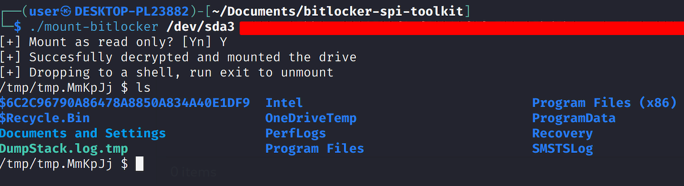
Access the Data: Once the drive is mounted, you will have full access to all the files and data stored on it.
Post-Exploitation
With the drive mounted and full read/write access to the file system, things get interesting. Because we’re modifying files offline while the OS isn’t running, we can completely sidestep runtime security controls like Endpoint Detection and Response (EDR) agents. This gives us a clean slate to establish persistence, dump credentials, or prep for the next pivot. Hell, if you wanted you could boot this up in a VM without a NIC attached and test local exploits against the laptop image without affecting the actual laptop.
Offline Credential Dumping
For pulling credentials, since we have offline access to the file system, we can extract the registry hives to grab local account password hashes. This means we can extract the domain machine account hash if the target is domain-joined.
Locate the Registry Hives: Navigate to
C:\Windows\System32\config\.Copy the Hives: Copy the
SAM,SECURITY, andSYSTEMfiles to your analysis machine.Dump Hashes with
secretsdump.py: Use Impacket’ssecretsdump.pyscript to perform an offline attack on the hives:1
secretsdump.py -sam SAM -system SYSTEM -security SECURITY LOCAL
This command will dump the NTLM hashes for all local users. These hashes can then be used in pass-the-hash attacks or cracked offline. If the machine is part of a domain, the machine account hash (e.g.,
LAPTOP-HOSTNAME$) will also be dumped. This hash can be used for lateral movement within the domain.
Establishing Persistence via Accessibility Features
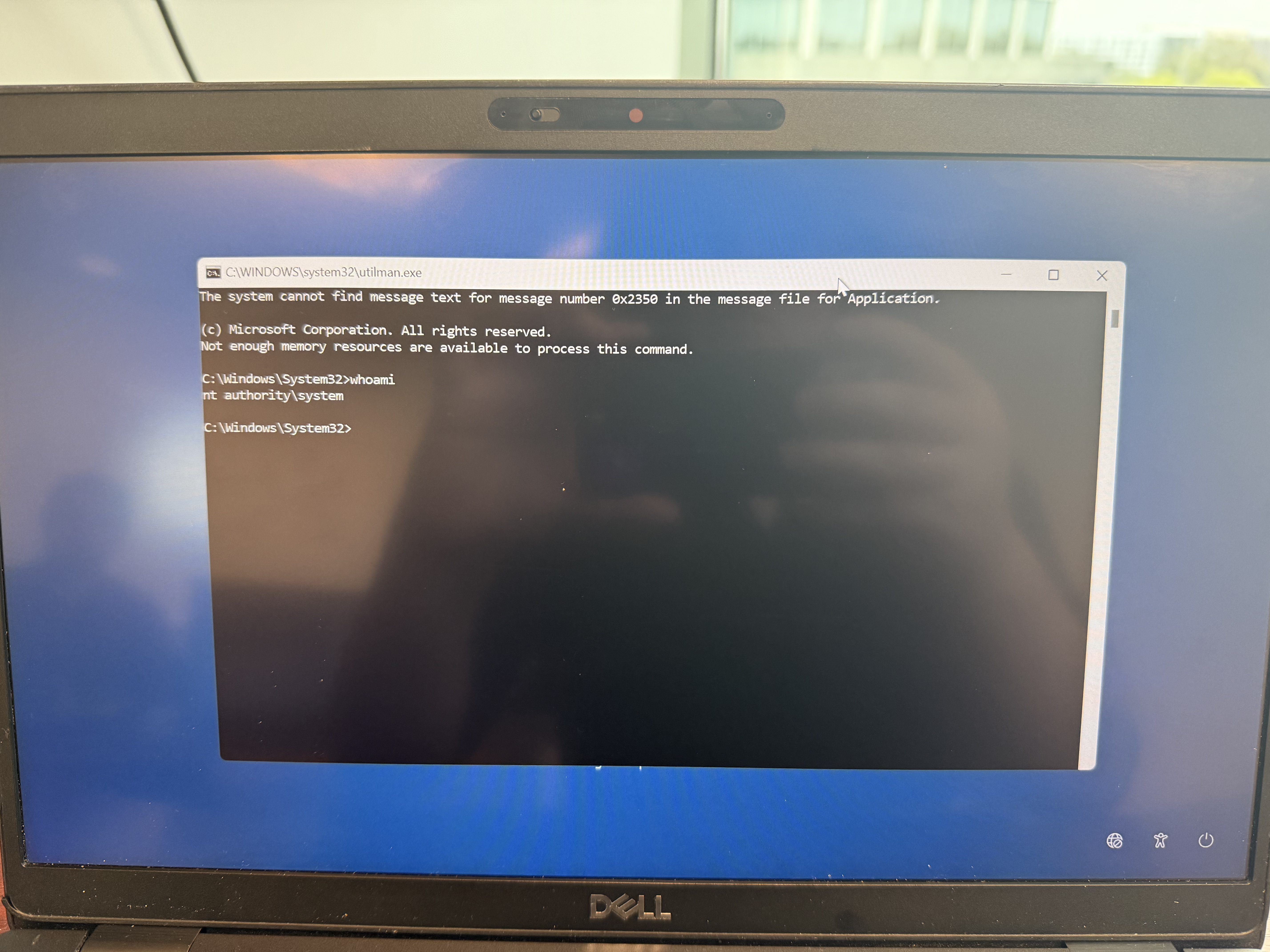
A classic technique for gaining persistent access is to replace one of the accessibility features available on the Windows lock screen with a command prompt. This allows an attacker to launch a SYSTEM-level shell without needing to log in.
- Navigate to the System32 Directory: Access the mounted Windows partition and go to the
C:\Windows\System32\directory. - Backup the Original Utility: Find
Utilman.exe(the Ease of Access button) and rename it toUtilman.exe.bak. This creates a backup of the original file. - Replace with Command Prompt: Make a copy of
cmd.exewithin the same directory and rename the copy toUtilman.exe.
After reassembling the laptop and booting it up, clicking the “Ease of Access” icon on the Windows login screen will now launch a command prompt running with NT AUTHORITY\SYSTEM privileges.
Disabling Security Software
EDR and antivirus solutions are designed to prevent malicious activity on a running system. By modifying their files while the system is offline, it’s possible to neutralize them before they can even start.
- Locate Security Agent Directories: Navigate to directories where EDR products may keep their files (e.g.,
C:\Program Files\,C:\Program Files (x86)\,C:\Windows\System32\drivers\). - Identify and Rename Directories: Look for folders corresponding to security products installed on the system, such as:
CrowdStrikeSentinelOneWindows Defender(Note: This is more complex as it’s a core OS component)Carbon Black
- Rename the Folder: Rename the main folder of the security product (e.g., rename
SentinelOnetoSentinelOne_Bak).
When the system boots up again, the security agent’s services will fail to find their necessary files and will not start, leaving the system unprotected and allowing you to execute further payloads without detection.
Warning: By renaming these files/folders, there is a chance that you may cause the system to experience a Blue Screen of Death (BSOD) on boot. This is particularly true when removing “boot first” drivers, such as SentinelOne and Crowdstrike’s files in C:\Windows\System32\drivers\. You will have to mess with different combinations of what you do and do not rename to get the system to boot again.
Defending Against the Attack
At the end of the day, this physical attack only works because of BitLocker’s default, convenience-first configuration. It’s technically effective in that state, but mitigating the sniffing threat is sometimes necessary depending on your risk tolerance and security requirements. For mitigation, our goal is to prevent the TPM from automatically releasing the Volume Master Key (VMK) at boot without some form of additional explicit user interaction.
Primary Mitigation: Pre-Boot Authentication (PBA)
The single most effective countermeasure is to require Pre-Boot Authentication (PBA). Instead of relying solely on the TPM, this method requires the user to provide a secret before the Windows boot process begins. This secret can be a PIN or a startup key stored on a USB drive. When PBA is enabled, the TPM will not release the VMK until the correct secret has been provided, rendering the bus sniffing attack ineffective as the key is never transmitted in a vulnerable state.
How to Enable Pre-Boot Authentication via Group Policy
For domain-joined machines or systems with access to the Local Group Policy Editor, this is the most reliable way to enforce PBA.
Open Group Policy Editor: Press
Win + R, typegpedit.msc, and press Enter.Navigate to the BitLocker Policy: Go to the following path:
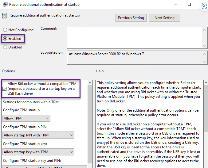
Computer Configuration > Administrative Templates > Windows Components > BitLocker Drive Encryption > Operating System Drives- Enable the “Require additional authentication at startup” Policy:
- Double-click this policy setting.
- Set it to Enabled.
- Under the “Options” pane, you can configure the specific protectors. For maximum security, uncheck “Allow BitLocker without a compatible TPM”.
- Configure TPM startup PIN to “Require startup PIN with TPM”.
- (Alternatively) Configure TPM startup key to “Require startup key with TPM”.
- (Optional) Enable Enhanced PINs: For stronger security, you can allow alphanumeric PINs instead of just numbers.
- In the same Group Policy location, enable the “Allow enhanced PINs for startup” policy.
- Apply the Policy: Run
gpupdate /forcefrom an administrative command prompt to apply the policy immediately.
Adding the Protector with manage-bde
After the policy has been applied, the new protector must be added to the existing BitLocker volume.
Open an Administrative Command Prompt or PowerShell.
Add the TPM+PIN Protector: Execute the following command:
1
manage-bde -protectors -add C: -TPMAndPIN
You will be prompted to enter and confirm your desired PIN.
(Alternative) Add the TPM+Startup Key Protector:
1
manage-bde -protectors -add C: -TPMAndStartupKey E:
Replace
E:with the drive letter of the USB drive where the startup key should be stored.Verify the Protectors: You can check that the new protector was added correctly by running:
1
manage-bde -status C:
The output should now list “TPM and PIN” or “TPM and Startup Key” under the “Key Protectors” section.
Secondary Mitigations and Defense-in-Depth
While PBA is the primary fix, other layers can increase the difficulty for an attacker.
- Hardware Selection (fTPM): Modern CPUs from Intel (Platform Trust Technology - PTT) and AMD (fTPM) integrate TPM functionality directly into the CPU’s firmware. Since there is no external chip or bus to sniff, these Firmware-based TPMs (fTPMs) are not vulnerable to this physical attack. When procuring new hardware, selecting systems with fTPMs is a significant security enhancement.
- UEFI/BIOS Password: Setting a strong password in the UEFI/BIOS settings adds a crucial hurdle. It can prevent an attacker from booting from an external device, modifying the boot order, or changing hardware settings, all of which may be necessary to carry out other related attacks.
- Physical Security: This attack requires sustained physical access to the device’s internals. Implementing strong physical security controls, such as secure storage for laptops, access control to facilities, and tamper-evident seals, is a fundamental and effective deterrent.
Factors Preventing Mitigation (Client Considerations)
Implementing these mitigations is not always straightforward, and folks may have valid operational reasons for hesitating. It’s important to understand and address these concerns.
User Friction and Help Desk Burden: The most common objection to enabling a pre-boot PIN is the impact on user experience. Users must enter a PIN every time they reboot their machine, which can be seen as an inconvenience. This also leads to an increase in help desk tickets for forgotten PINs. If a PIN is forgotten, the only recourse is the 48-digit BitLocker Recovery Key, which can be cumbersome for support staff to provide and for users to enter.
Remote Management and Automation: PBA breaks many remote management workflows. If an administrator needs to reboot a fleet of machines remotely to apply patches, they cannot enter the BitLocker PIN. This means a machine will not fully boot until someone physically enters the PIN, disrupting maintenance windows and creating significant operational overhead. While solutions like Intel vPro or remote KVMs can sometimes help, they are not universally deployed.
Deployment at Scale: In environments without robust, centralized management tools like Microsoft Group Policy or Intune, enforcing these settings on every endpoint is a major challenge. Manually configuring each machine is not feasible for large organizations.
Hardware Limitations: The recommendation to use fTPM over dTPM is only practical during a hardware refresh cycle. Most organizations have a fleet of devices with varying hardware ages and cannot simply replace all vulnerable dTPM-based systems overnight due to budget constraints.
Resources
- TPM 2.0: Extracting Bitlocker keys through SPI: https://lucasteske.dev/2024/01/tpm2-bitlocker-keys
- Extracting BitLocker keys from a TPM: https://pulsesecurity.co.nz/articles/TPM-sniffing
- BitLocker Overview: https://learn.microsoft.com/en-us/windows/security/operating-system-security/data-protection/bitlocker/
- Microsoft BitLocker Group Policy Reference: https://learn.microsoft.com/en-us/windows/security/operating-system-security/data-protection/bitlocker/bitlocker-group-policy-settings
manage-bdeCommand-Line Reference: https://learn.microsoft.com/en-us/windows-server/administration/windows-commands/manage-bde- BitLocker Countermeasures: https://learn.microsoft.com/en-us/windows/security/operating-system-security/data-protection/bitlocker/countermeasures